|
|
|
Baby's First Hardware Prototype |
|||||||||||||||||||||||||||
| Before you start to build your prototype: | |||||||||||||||||||||||||||
|
|||||||||||||||||||||||||||
| 5) In troubleshooting:
Don't be shy about trying several NEW parts--you could have a bad part! This includes resistors and caps. Also, remember more than 80% of all problems could have been found using your EYES! You may be using a resistor for Ra or Rb that is too low in value, e.g., the 555 doesn't like Ra values below ~5K. 7) Pin 5--the Voltage Control pin
of a 555 timer must be A.C. coupled! If you Direct Couple pin-5, you force
a bias on it that could prevent it from ever charging the timing cap to
2/3 Vcc
8) DO NOT use electrolytic for the timing caps. |
|||||||||||||||||||||||||||
| When
prototyping your first circuit:
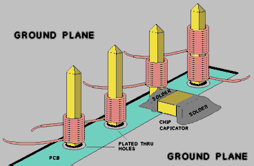
1) The circuit should be put on a printed circuit board (PCB) 2) having lots of groundplane; 3) plated thru holes; 4) the interconnection should be "Wire Wrap" using 5) 30 Ga., kynar insulated, WW Wire. 6) The Sockets should be of the Machined-Pin, Wire Wrap types; 7) All Components (except bypass capacitors & Voltage Regulator components--components that will never change their required value) should be "plugged" into the same type of sockets and their position should be as close to the other components they are connected to: Wire Wrap Machined sockets 8) Once completed, the WW socket Pins can & should be cut short--reducing stray parasitic inductance and capacitance. 9 Power Supplies: should be, either "Hard Wired" to the circuit of interest, or plugable using the following precautions: a.. If there is more than one voltage involved, e.g., +/- 12-V: install ~ >1 amp reversed diodes across the input of each power input. This will prevent "Circuit Injury" due to reverse voltages. This has to do with "Hot Plugging." |
|||||||||||||||||||||||||||
DO's |
DON'Ts |
| 1)
The circuit should be put on a printed circuit board (PCB).
2) The PCB Should have lots of groundplane. 3) The PCB Should have plated thru holes. 4) Use Wire Wrap interconnections. 5) Only 30 Ga., kynar insulated, WW Wire. 6) The Sockets should be of the Machined-Pin, Wire Wrap types. 7) All Components (except bypass capacitors
& Voltage Regulator components--components that will never change their
required value) should be "plugged" into the same type of sockets and their
position should be as close to the other components they are connected
to.
9) Power Supplies: either "Hard Wired" to the circuit of interest, Or plugable using protection. 10) When dealing with multiple wires as in a bus, always seperate them --Never "Bundle." 11) Never plug & unplug your circuit from the powersupply while it is ON. Disconnect the power supply from the Mains (120 VAC). 12) Always make perminent connections to the powersupply: 13) Always Power Down--and wait n seconds--before pluging in ANY component. 13 a.) Always, FIRST make electical contact with the circuit board's COMMON (grabing circuit's Grd. with the other hand) before plugging in any Semiconductor device. |
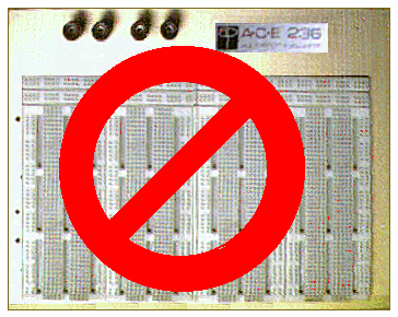
1)
NEVER EVER use the white nylon plug-boards that you have used in your previous
"Labs."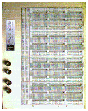
2) Never Solder wires (except for Bypass capacitors & power supplies).: Use Wire Wrap. 3) Never use bare "Perf-Boards" that have no copper layer(s) or plated thru holes. 4) Never use "Hand" wire Wrap tools--always use WW Guns! 5) Never use any Socket that isn't Machined-Pin. 6) Never use etched or milled PCBs for your very First prototype board. 8) Never use excessive wire length. 9)Never leave WW sockets with unnecessary pin length. 10) Never run many wires(e.g, digital bus) close togather--Never "Bundle" them. 11) Never plug & unplug your circuit from the powersupply while it is ON. 12) Never make "Temporary (e.g., aligator clips) connections to the powersupply: Always make them perminent. 13) Never plug in any device to a circuit while it is powered! 14 a.) Never plug in a Semiconductor device without FIRST making electical contact with the circuit board's COMMON (grabing circuit's Grd. with the other hand). |
The white nylon proto-boards are constructed for ease and speed of use;
however they
The resulting circuit design that one "made to work" on the proto-board,
can end up not
If the rules (data sheet) aren't followed you can have some pretty weird
things
|
|