| Sounds
Automotive Doppler Radar |
|
|
Travling
thru an UnderPass
|
| Introduction
A system for the detection and tracking of vehicles approaching from the rear, such that an adaquite warning envelop is created around the vehicle-to-be-warned (VTBW). That is to say, if I choose to change lanes, such a system would warn [1] me of any hazard or potential hazard in the intended lane. |
 |
|
|
 |
|
|
 |
|
|
|
|
| Introduction
A system for the detection and tracking of vehicles approaching from the rear, such that an adaquite warning envelop is created around the vehicle-to-be-warned (VTBW). That is to say, if I choose to change lanes, such a system would warn [1] me of any hazard or potential hazard in the intended lane. Using an assortment of microwave transmitters, receivers and transceivers (operating at frequencies of 10 GHz, 25 GHz, and sweepable 10 GHz to 30 GHz) the system will basically work as follows: There will be one emitter located at the rear center--near the CHMSL--and it will have a rather broad beamwidth in the horizontal plane (covers three lanes). There will be four receivers (having narrower beamwidth), two mounted on each side of the vehicle--one high, one low--both aimed straight back. (I am using only one on a side for now.) Three modes:
2) Mode 2, Differential:
3) Mode 3, Range:
At a distance = 1/4 wavelength of the modulating sinusoid, the reflected carrier at the receiver--after demodulation--will be 180 degrees out of phase (null) from the originating modulating wave. Knowing the exact frequency of the modulating wave, the approximate distance to the target can be derived. (remember, 1/4 wavelength is the round-trip distance for 180 degrees or1/2 wavelength) Note, there will be some error in this approach if the rate of sweep--of the modulating wave, verses the range isn't accounted for. As the modulating frequency continues to increase, the 180 degree "null" will again occur when the modulating frequency is 1.5 times the first null frequency (fm); this will continue to occur every additional half wavelength, i.e., 1.5 fm, 3.5 fm, 5.5 fm, 7.5 fm, etc.--each time resolving the distance ever finer. That is: 1/2 WL at 10 MHz is a finer unit of measurement than 1/2 WL at 1 MHz. All three modes will be used in combination in a very rapid fashion. (limited by PRF, Doppler frequencies at n x MPH @ m x GHz, as well as, the sweep rate of the modulating frequencies, fm) Summary:
This is a daunting task: because of the high reliability needed, the operating environment, the kinds of information needed, the finite time allotted for its detection and interpretation, and the cost target as an automotive OEM device It is a given, that the success of this approach will depend, in great measure, on good signal processing (DSP) techniques.
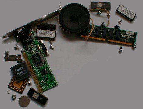
Learning Curve Playing with a Doppler RADAR device made from a modified "fuzz-Buster" with the intentions of better understanding the characteristics of ~ 25 GHz Doppler. With an assortment of microwave transmitters, receivers and transceivers--10 GHz, 25 GHz, and a sweepable 10 GHz to 30 GHz--to test an idea I have. |
System for Vehicle Blind-Spot Enervation